so, hier nochmal die "fast" bauanleitung, für denjenigen der sich sowas selbst basteln will:
Kabel, je nach bedarf. Ich hab das ganze mit RJ-12 buchsen und 10m kabel verlegt.
-Stromversorgung für den Arduino beschreibe ich nicht, das ist bei jedem anders. Er akzeptiert alles zwischen 6 und 20V. Wer also 12V irgendwo rumliegen hat, kann das wunderbar verwenden.
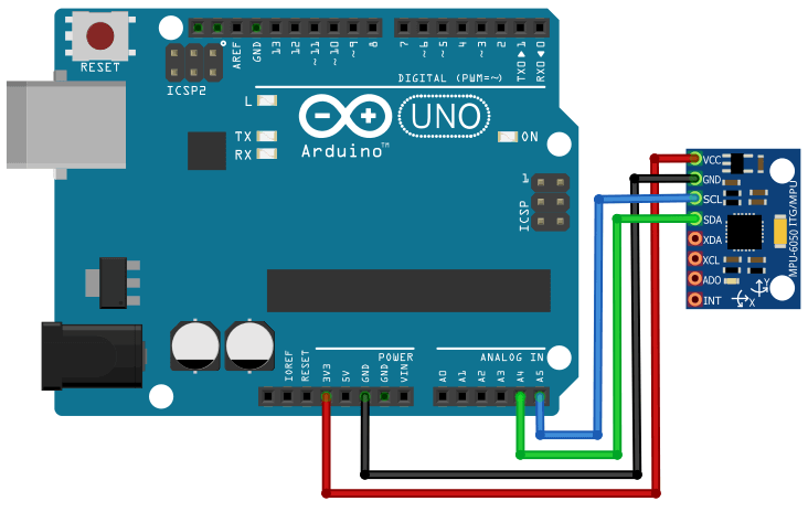
-Den Sensor mit dem Arduino verkabeln! Achtung: Durch das DisplayShield sind die origina-pins des arduino nichtmehr zu erreichen. Diese werden aber ans Shield durchgereicht, können also bequem am Shield angelötet werden
-Beim starten des scripts wird im Terminal des PC´s die Fehlerwerte des sensors ausgegeben. Diese sind in das script an markierter position einzugragen (GyroErrorX, GyroErrorY, GyroErrorZ, AccErrorX und AccErrorY)
Der Arduino zeigt die Neigung der PITCH achse im Display an. Mit drücken der "up" taste kann das ergebnis auch "genullt" werden. Hier kann jeder nach seinem einbau auch selbst einen fixen offset-wert eintragen! Das liegt an euch....
Code: Alles auswählen
#include <Wire.h>
#include <LiquidCrystal.h>


const int MPU = 0x68; // MPU6050 I2C address
float AccX, AccY, AccZ;
float GyroX, GyroY, GyroZ;
float accAngleX, accAngleY, gyroAngleX, gyroAngleY, gyroAngleZ;
float roll, pitch, yaw;
float AccErrorX, AccErrorY, GyroErrorX, GyroErrorY, GyroErrorZ;
float elapsedTime, currentTime, previousTime;
int c = 0;

const int rs = 8, en = 9, d4 = 4, d5 = 5, d6 = 6, d7 = 7;
LiquidCrystal lcd(rs, en, d4, d5, d6, d7);


int button = 0;
float angleoffset = 0;

int rest = 0;


byte p2[8] = {
  0b10000,
  0b10000,
  0b10000,
  0b10000,
  0b10000,
  0b10000,
  0b10000,
  0b10000
};

byte p4[8] = {
  0b11000,
  0b11000,
  0b11000,
  0b11000,
  0b11000,
  0b11000,
  0b11000,
  0b11000
};

byte p6[8] = {
  0b11100,
  0b11100,
  0b11100,
  0b11100,
  0b11100,
  0b11100,
  0b11100,
  0b11100
};

byte p8[8] = {
  0b11110,
  0b11110,
  0b11110,
  0b11110,
  0b11110,
  0b11110,
  0b11110,
  0b11110
};


byte p10[8] = {
  0b11111,
  0b11111,
  0b11111,
  0b11111,
  0b11111,
  0b11111,
  0b11111,
  0b11111
};

byte n2[8] = {
  0b00001,
  0b00001,
  0b00001,
  0b00001,
  0b00001,
  0b00001,
  0b00001,
  0b00001
};


byte n4[8] = {
  0b00011,
  0b00011,
  0b00011,
  0b00011,
  0b00011,
  0b00011,
  0b00011,
  0b00011
};

byte n6[8] = {
  0b00111,
  0b00111,
  0b00111,
  0b00111,
  0b00111,
  0b00111,
  0b00111,
  0b00111
};

byte n8[8] = {
  0b01111,
  0b01111,
  0b01111,
  0b01111,
  0b01111,
  0b01111,
  0b01111,
  0b01111
};


void setup() {
  Serial.begin(115200);
  Wire.begin();                      // Initialize comunication
  Wire.beginTransmission(MPU);       // Start communication with MPU6050 // MPU=0x68
  Wire.write(0x6B);                  // Talk to the register 6B
  Wire.write(0x00);                  // Make reset - place a 0 into the 6B register
  Wire.endTransmission(true);        //end the transmission

  // Call this function if you need to get the IMU error values for your module

  calculate_IMU_error();


  lcd.createChar(3, p10);


  delay(20);


  lcd.begin(16, 2);
  lcd.clear();

}

void loop() {
  button = analogRead(A0);


  get_angle();
  pitch = pitch - angleoffset;
  draw_angles2();


  // Print the values on the serial monitor
  /*
    Serial.print(roll);
    Serial.print("/");
    Serial.print(pitch);
    Serial.print("/");
    Serial.println(yaw);

  */

  Serial.println(button);

  if (button == 639) {
    get_angle();
    angleoffset = pitch;
  }

  delay(200);
}


void draw_angles2() {
  lcd.clear();

  rest = 10 * (pitch - int(pitch));


  if (rest <= -8) {
    lcd.createChar(4, n8);
  }
  else if (rest <= -6) {
    lcd.createChar(4, n6);
  }
  else if (rest <= -4) {
    lcd.createChar(4, n4);
  }
  else if (rest <= -2) {
    lcd.createChar(4, n2);   //n2
  }
  else if (rest <= 2) {
    lcd.createChar(4, p2);
  }
  else if (rest <= 4) {
    lcd.createChar(4, p4);
  }
  else if (rest <= 6) {
    lcd.createChar(4, p6);
  }
  else if (rest <= 8) {
    lcd.createChar(4, p8);
  }

  //delay(50);


  if (pitch < 0) {
    if (rest <= -2) {
      lcd.setCursor(7 + int(pitch), 0);
      lcd.write(4);
    }
    if (pitch < -1) {
      for (int i = 8 + int(pitch); i <= 7; i++) {
        lcd.setCursor(i, 0);
        lcd.write(3);
      }
    }
  }
  else {   //pitch >0

    if (rest >= 2) {
      lcd.setCursor(8 + int(pitch), 0);
      lcd.write(4);
    }
    if (pitch > 1) {
      for (int i = 8; i <= 7 + int(pitch); i++) {
        lcd.setCursor(i, 0
        lcd.write(3);
      }

    }

  }

  lcd.setCursor(0, 1);
  lcd.print("Angle: ");

  //  lcd.print(rest);

  if (pitch < 0) {
    lcd.setCursor(7, 1);
  }
  else {
    lcd.setCursor(8, 1);
  }
  lcd.print(0.1 * int(pitch * 10));
  //lcd.print(pitch);

}


void draw_angles() {
  lcd.clear();
  //  lcd.setCursor(0, 0);


  if (pitch < 0) {
    for (int i = 7 + int(pitch * 2); i <= 7; i++) {
      lcd.setCursor(i, 0);
      lcd.print("#");
    }
  }
  else {   //pitch >0
    for (int i = 7; i <= 7 + int(pitch * 2); i++) {
      lcd.setCursor(i, 0);
      lcd.print("#");
    }

  }

  lcd.setCursor(0, 1);
  lcd.print("Pitch: ");

  if (pitch < 0) {
    lcd.setCursor(7, 1);
  }
  else {
    lcd.setCursor(8, 1);
  }
  lcd.print(0.1 * int(pitch * 10));
  //lcd.print(pitch);

}


void print_angles() {
  lcd.clear();
  lcd.setCursor(0, 0);
  lcd.print("Roll: ");
  lcd.setCursor(8, 0);
  lcd.print(roll);

  lcd.setCursor(0, 1);
  lcd.print("Pitch: ");
  lcd.setCursor(8, 1);
  lcd.print(pitch);
}

void get_angle() {


  // === Read acceleromter data === //
  Wire.beginTransmission(MPU);
  Wire.write(0x3B); // Start with register 0x3B (ACCEL_XOUT_H)
  Wire.endTransmission(false);
  Wire.requestFrom(MPU, 6, true); // Read 6 registers total, each axis value is stored in 2 registers
  //For a range of +-2g, we need to divide the raw values by 16384, according to the datasheet
  AccX = (Wire.read() << 8 | Wire.read()) / 16384.0; // X-axis value
  AccY = (Wire.read() << 8 | Wire.read()) / 16384.0; // Y-axis value
  AccZ = (Wire.read() << 8 | Wire.read()) / 16384.0; // Z-axis value
  // Calculating Roll and Pitch from the accelerometer data
  accAngleX = (atan(AccY / sqrt(pow(AccX, 2) + pow(AccZ, 2))) * 180 / PI) - 3.09; // AccErrorX ~(0.58) See the calculate_IMU_error()custom function for more details
  accAngleY = (atan(-1 * AccX / sqrt(pow(AccY, 2) + pow(AccZ, 2))) * 180 / PI) - 3.9; // AccErrorY ~(-1.58)

  // === Read gyroscope data === //
  previousTime = currentTime;        // Previous time is stored before the actual time read
  currentTime = millis();            // Current time actual time read
  elapsedTime = (currentTime - previousTime) / 1000; // Divide by 1000 to get seconds
  Wire.beginTransmission(MPU);
  Wire.write(0x43); // Gyro data first register address 0x43
  Wire.endTransmission(false);
  Wire.requestFrom(MPU, 6, true); // Read 4 registers total, each axis value is stored in 2 registers
  GyroX = (Wire.read() << 8 | Wire.read()) / 131.0; // For a 250deg/s range we have to divide first the raw value by 131.0, according to the datasheet
  GyroY = (Wire.read() << 8 | Wire.read()) / 131.0;
  GyroZ = (Wire.read() << 8 | Wire.read()) / 131.0;
  // Correct the outputs with the calculated error values
  GyroX = GyroX + 3.1; // GyroErrorX ~(-0.56)
  GyroY = GyroY - .02; // GyroErrorY ~(2)
  GyroZ = GyroZ + 0.17; // GyroErrorZ ~ (-0.8)

  // Currently the raw values are in degrees per seconds, deg/s, so we need to multiply by sendonds (s) to get the angle in degrees
  gyroAngleX = gyroAngleX + GyroX * elapsedTime; // deg/s * s = deg
  gyroAngleY = gyroAngleY + GyroY * elapsedTime;
  yaw =  yaw + GyroZ * elapsedTime;

  // Complementary filter - combine acceleromter and gyro angle values
  //roll = 0.96 * gyroAngleX + 0.04 * accAngleX;
  //pitch = 0.96 * gyroAngleY + 0.04 * accAngleY;


  float cfac = .04;  // TEST ml
  //roll =  (1-cfac)* gyroAngleX + cfac * accAngleX;  //TEST ml
  //pitch = (1-cfac) * gyroAngleY + cfac * accAngleY;  //TEST ml


  roll =  accAngleX;
  pitch = accAngleY;
}

void calculate_IMU_error() {
  // We can call this funtion in the setup section to calculate the accelerometer and gyro data error. From here we will get the error values used in the above equations printed on the Serial Monitor.
  // Note that we should place the IMU flat in order to get the proper values, so that we then can the correct values
  // Read accelerometer values 200 times
  while (c < 200) {
    Wire.beginTransmission(MPU);
    Wire.write(0x3B);
    Wire.endTransmission(false);
    Wire.requestFrom(MPU, 6, true);
    AccX = (Wire.read() << 8 | Wire.read()) / 16384.0 ;
    AccY = (Wire.read() << 8 | Wire.read()) / 16384.0 ;
    AccZ = (Wire.read() << 8 | Wire.read()) / 16384.0 ;
    // Sum all readings
    AccErrorX = AccErrorX + ((atan((AccY) / sqrt(pow((AccX), 2) + pow((AccZ), 2))) * 180 / PI));
    AccErrorY = AccErrorY + ((atan(-1 * (AccX) / sqrt(pow((AccY), 2) + pow((AccZ), 2))) * 180 / PI));
    c++;
  }
  //Divide the sum by 200 to get the error value
  AccErrorX = AccErrorX / 200;
  AccErrorY = AccErrorY / 200;
  c = 0;
  // Read gyro values 200 times
  while (c < 200) {
    Wire.beginTransmission(MPU);
    Wire.write(0x43);
    Wire.endTransmission(false);
    Wire.requestFrom(MPU, 6, true);
    GyroX = Wire.read() << 8 | Wire.read();
    GyroY = Wire.read() << 8 | Wire.read();
    GyroZ = Wire.read() << 8 | Wire.read();
    // Sum all readings
    GyroErrorX = GyroErrorX + (GyroX / 131.0);
    GyroErrorY = GyroErrorY + (GyroY / 131.0);
    GyroErrorZ = GyroErrorZ + (GyroZ / 131.0);
    c++;
  }
  //Divide the sum by 200 to get the error value
  GyroErrorX = GyroErrorX / 200;
  GyroErrorY = GyroErrorY / 200;
  GyroErrorZ = GyroErrorZ / 200;
  // Print the error values on the Serial Monitor
  Serial.print("AccErrorX: ");
  Serial.println(AccErrorX);
  Serial.print("AccErrorY: ");
  Serial.println(AccErrorY);
  Serial.print("GyroErrorX: ");
  Serial.println(GyroErrorX);
  Serial.print("GyroErrorY: ");
  Serial.println(GyroErrorY);
  Serial.print("GyroErrorZ: ");
  Serial.println(GyroErrorZ);

  //delay(5000);
}